Modified by Jason Marmon and George Lisensky from J. J. Garcia-Jareño,
D. Benito, J. Navarro-Laboulais, and F. Vicente, "Electrochemical Behavior of
Electrodeposited Prussian Blue Films on ITO Electrodes," J. Chem. Educ.,
75, 881-884 (1998).
Prussian Blue, Fe(III)4[Fe(II)(CN)6]3.xH2O (Click for jmol), is strongly colored and has been made by chemists for 300 hundred years. For more information on
its history, see C&E News, 83(18), 32-35 (2005) or Pigments through the Ages.
In this experiment [Fe(III)(CN)6]-3 is electrochemically reduced on a glass electrode to produce [Fe(II)(CN)6]-4.
The [Fe(II)(CN)6]-4 formed at the electrode reacts with Fe(III)Cl3 in solution to give insoluble Prussian Blue on the electrode.
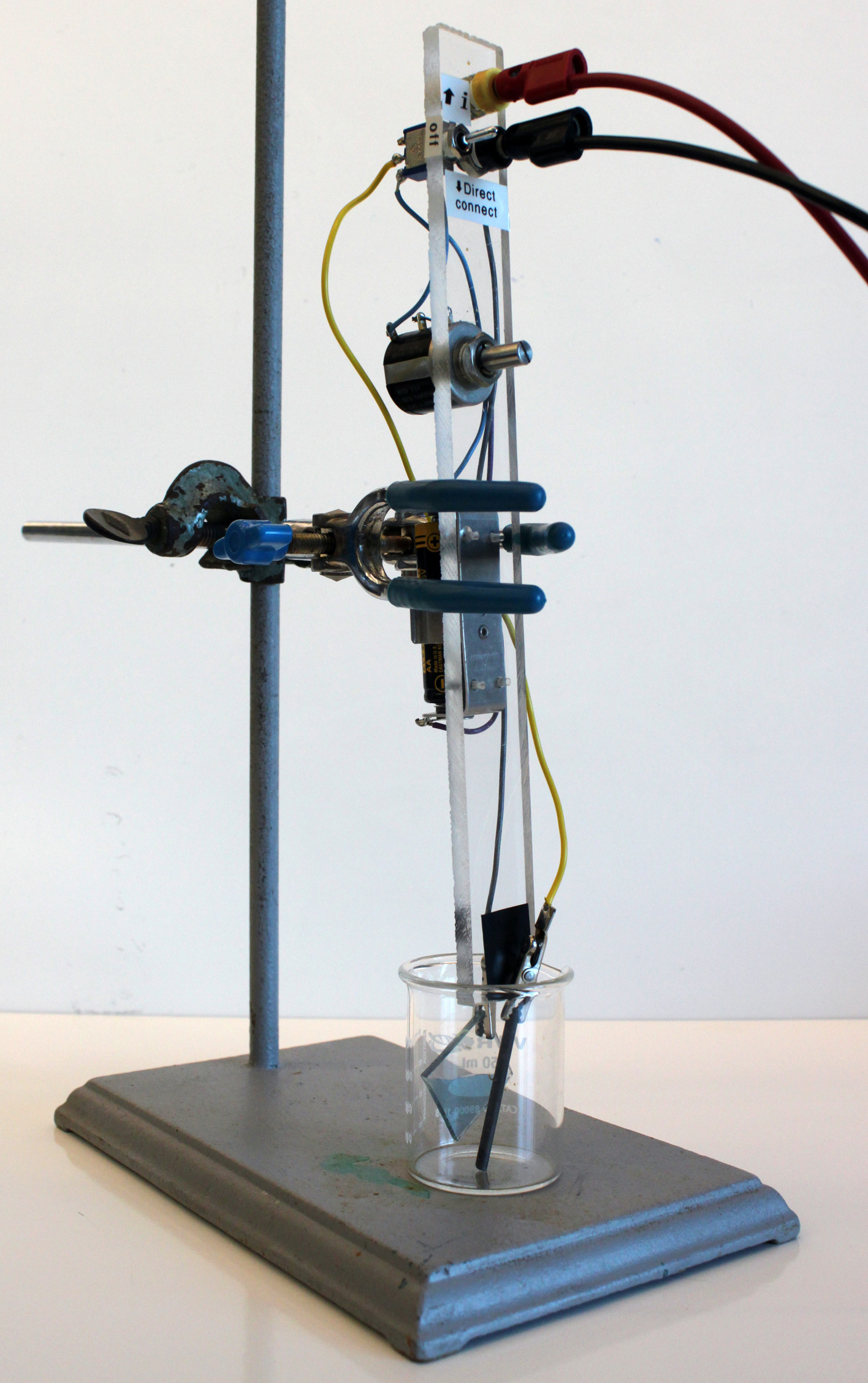
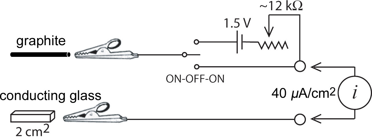
You will use an electrical circuit (see diagram below) to supply current for a known number of seconds. Knowing the current, the amount of time, and the electrode area lets you calculate the coating thickness.
(The sixth term in the equation above comes from the cubic unit cell dimensions. Inorg. Chem., 16(11), 2704-2710, (1977)).
What is the minimum thickness of Prussian Blue that can be seen by eye?
Does the coating on the glass change color with applied voltage, i.e., does a 200 nm thick layer of Prussian Blue exhibit electrochromism? Electrochromic displays, where an electrochemical redox reaction changes the pixel state,
do not need constant application of power. Such pixels are useful for electronic books where high contrast and low power consumption are important and for smart windows to reduce energy use.
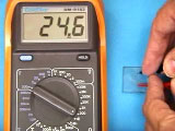
Obtain two cables, a multimeter, and a tin oxide-coated glass square. Set the multimeter to measure resistance (Ω). What reading do you get when the cables are touching? What reading do you get when the cables are not touching? (The latter is an open circuit with a very large resistance.)
Identify the conducting side of the glass square. The conducting side will have a resistance of 20-30 ohms and the non-conducting side will have a very large resistance.
Obtain a battery and circuit, clamp and ringstand, a graphite electrode, and a 50 mL beaker.
Set the multimeter to measure dc voltage. Record the voltage of the 1.5 V battery. Place the battery in its holder with the + on the battery matching the + on the holder.
Clamp the circuit to a ringstand.
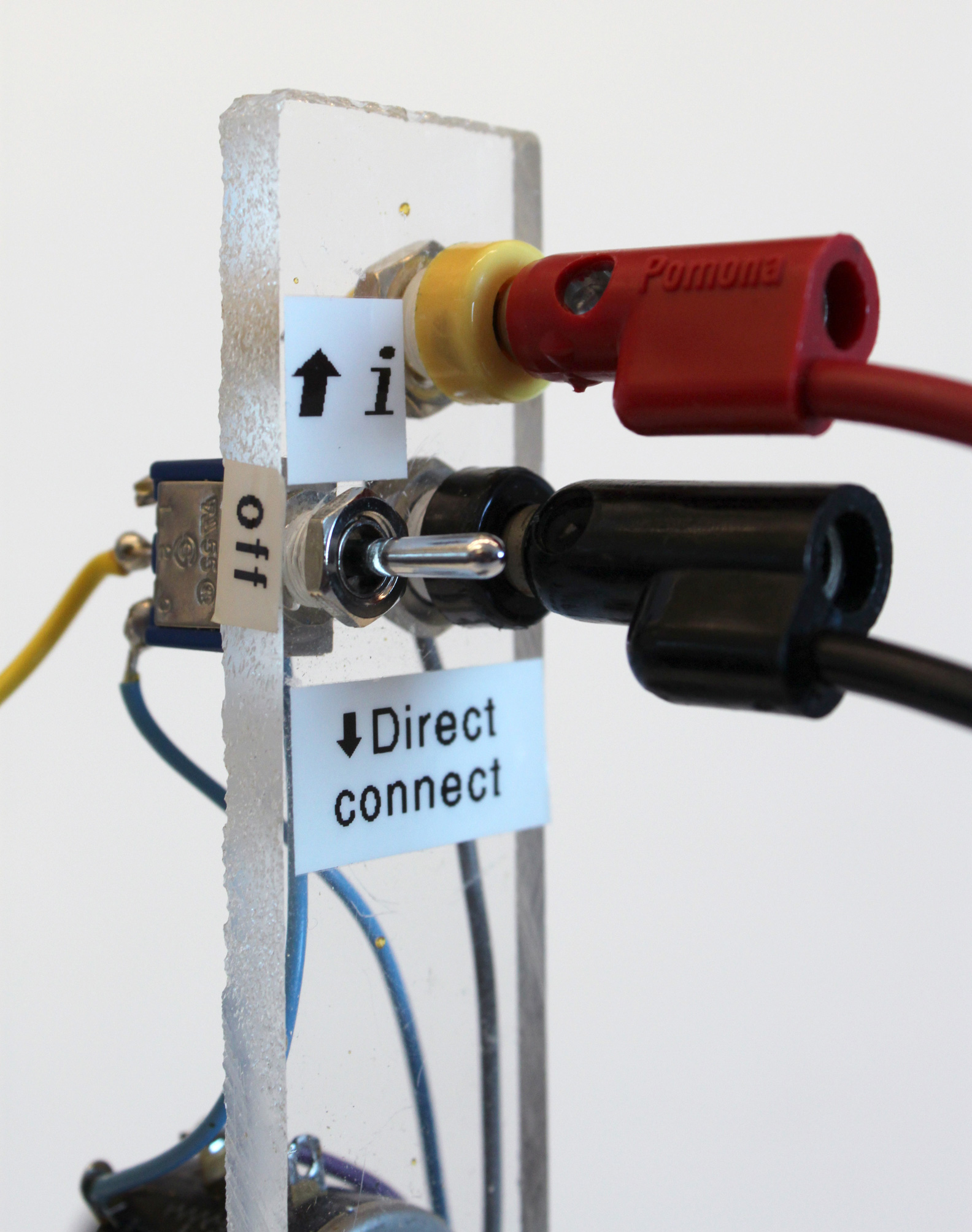
Set the toggle switch (see right) to the center position (off).
Connect the cables to the multimeter and set it to read µA.
Connect the graphite electrode to the long lead. (This connects the positive lead of the voltage source to the graphite electrode.)
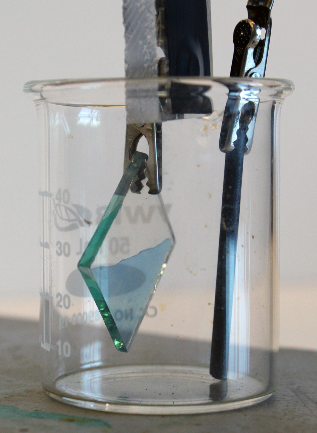
Connect the glass to the aligator clip on the plastic holder. (This connects the negative lead of the voltage source to the glass so electrons will be supplied to the glass when the switch is on.) Face the conducting side of the glass (see above) towards the graphite electrode.
Adjust the height so that when there is 25 mL of solution in the beaker, the aligator clip will not dip into the solution. If the aligator clip touches the solution the product will not be formed on the glass.
How many cm2 will you be coating? To get 40µA/cm2 how many µA should be used? You must do this calculation before continuing.
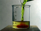
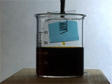
Add 5 mL 0.05 M HCl, then 10 mL 0.05 M K3[Fe(CN)6],
and then 10 mL 0.05 M FeCl3.6H2O to a
50 mL beaker. The mixed solution should be prepared shortly before use.
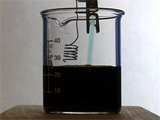
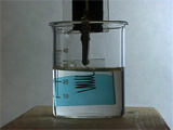
Position the electrodes (but not the aligator clips) in the solution. While watching the µA reading on the multimeter, move the toggle switch to i
and immediately turn the metal shaft on the variable resistor to adjust the µA to the desired setting. Continue to adjust as needed to keep a constant current.
To stop, move the toggle switch to the center position (off). Be sure to keep track of the total number of seconds that the current is on.
Examine the glass electrode at intermediate times (every 10 or 15 seconds) by removing and rinsing with water. How many total seconds are need to provide a coating that you can see?
Do longer depositions give a darker color?
Option: Rinse the electrode with pure water and then measure the visible absorbance (690 nm) as a function of layer thickness.
After you have determined the minimum coating thickness that can be seen, continue the electrolysis for a total of 200-300 seconds to prepare a relatively thick film. Record the total seconds that current was applied to the sample. Rinse the electrode with water.
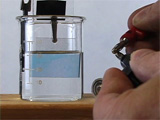
Place the rinsed electrodes in 25 mL 1.0 M KCl, keeping the clip above the solution.
Remove the battery and the multimeter from the circuit.
Move the toggle switch to the direct connect position so the cables connect directly to the electrodes in solution.
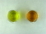
Connect the glass electrode to battery (–) and the graphite electrode connected to battery (+). Does the color change?
Touch the two cables together, i.e., complete the circuit with no battery. Does the color change?
Repeat the previous two steps several times. (Repetition is thought to make the film more stable for the next part.)
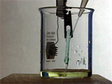
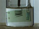
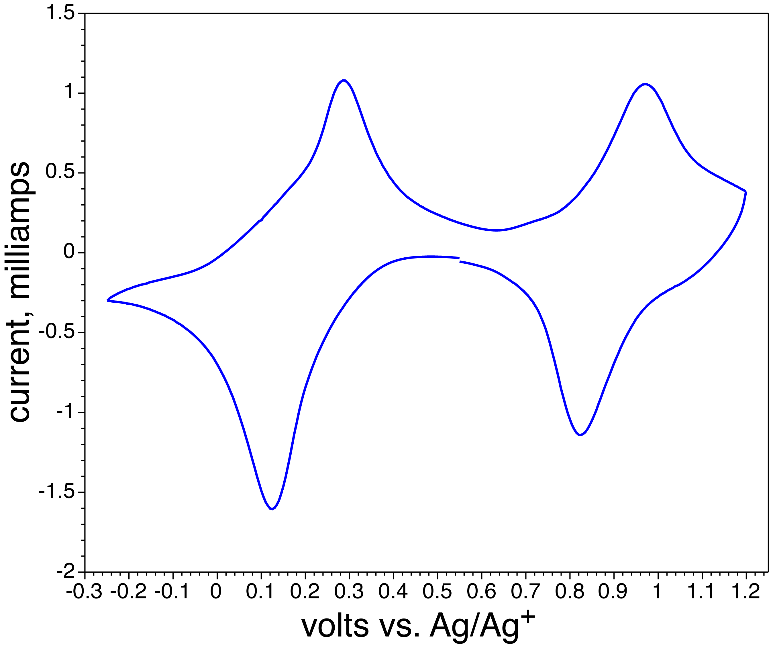
Record the cylic voltammogram using the Prussian Blue coated glass as the working electrode, the graphite as the auxiliary electrode, and a Ag/AgCl electrode as the reference electrode.
All three electrodes must be in the beaker.
Scan at 20 mV/sec from +550 mV to -250 mV to +1200 mV to +550 mV. See directions below. When the voltage matches a redox reaction the current increases. Does the color change at the same time?
Repeat the scan as necessary to observe the color changes.
Conclusions
How thin is the minimum coating you can see? How thick is the thickest film you made? Show your calculations.
What color is the reduction product of Prussian Blue? What is the redox potential for this reaction?
0.05 M HCl (Each preparation needs 5 mL. Dilute 5 mL conc HCl to 250
mL with water.)
0.05 M K3[Fe(CN)6] (Each preparation needs 10 mL.
Dissolve 1.65 g in 100 mL water.)
0.05 M FeCl3.6H2O (Each preparation needs
10 mL. Dissolve 1.35 g in 100 mL water with a drop of HCl.)
1.0 M KCl (Each preparation needs 25 mL. Dissolve 18.6 g in 250 mL water
with two drops of HCl to lower the pH.)
Equipment
50 mL beaker
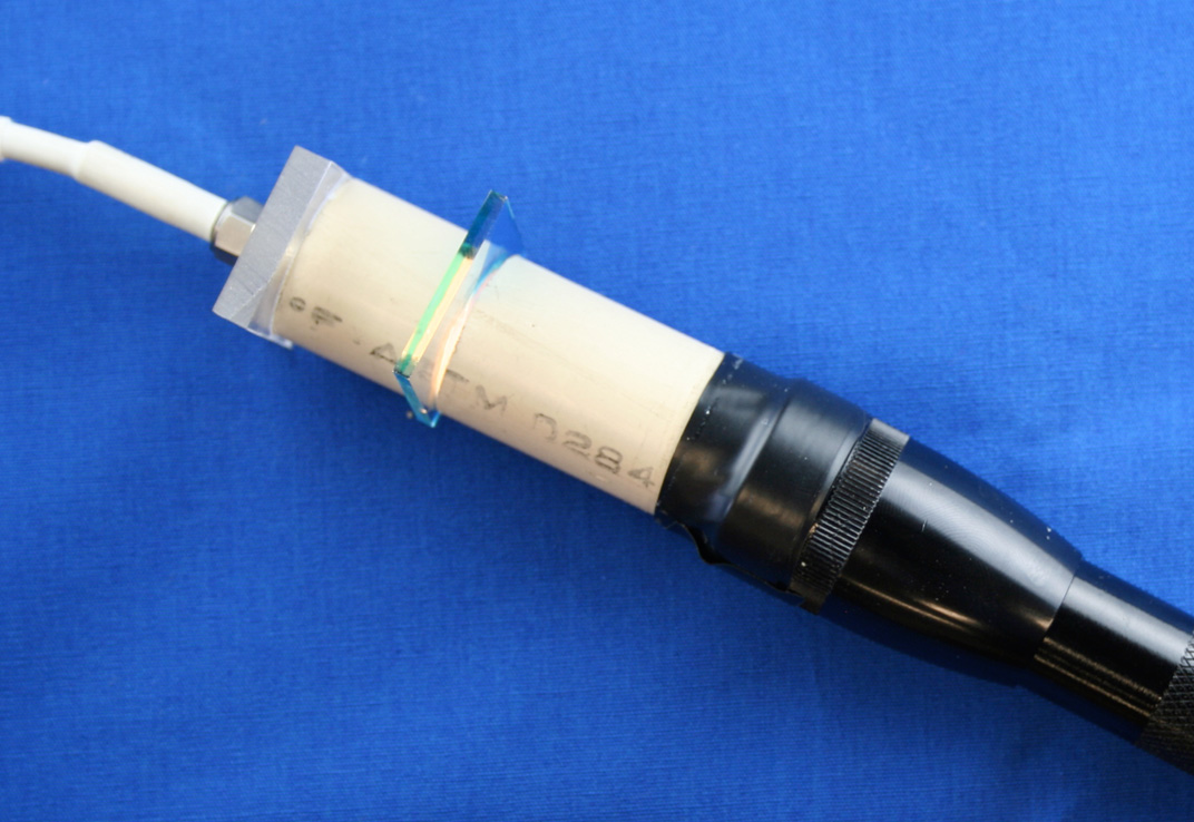
Conductive Glass (1" x 1" x 2.3mm TEC 15 glass) Hartford Glass Co, 735 E Water Street, Hartford City, IN 47348 Phone: 765-348-1282.
Glass can be reused by removing prussian blue coatings with concentrated ammonia (solubility increases with pH).
Multimeter for measuring resistance, voltage and current
Pt wire or graphite electrode
Ag/AgCl reference electrodes and electrochemical apparatus for obtaining cyclic voltammograms.
1.5 Volt battery, holder, and 50 K ohm variable resistor for controlling deposition current. Click image for larger view

 Click image for larger view
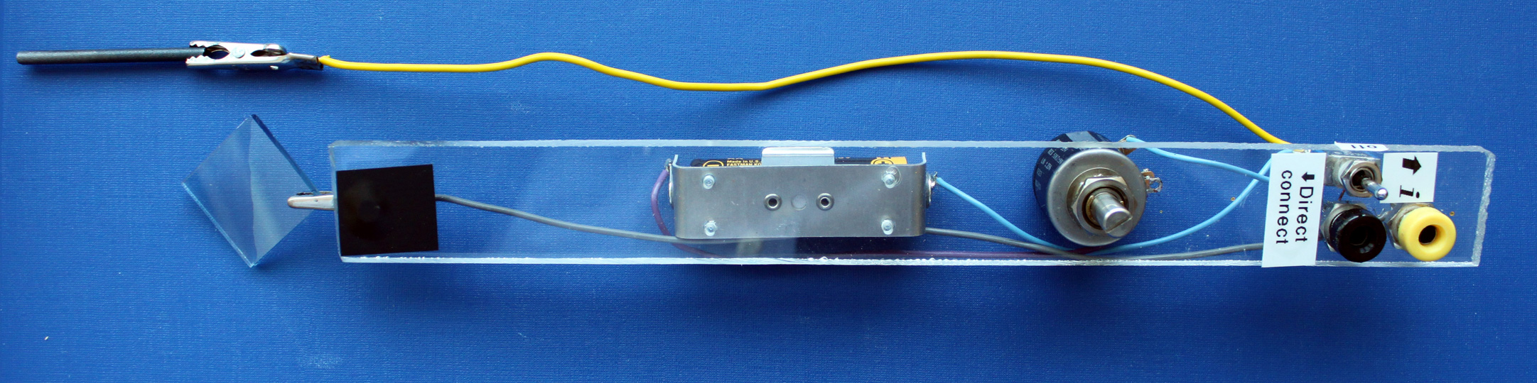 Click image for larger view